




























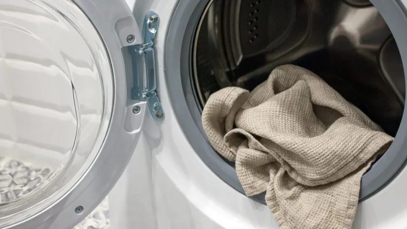
You probably don’t think about it when you pull out a warm towel. But inside that white box is a surprisingly simple machine. It pulls in air. Heats it up. Blows it through wet clothes. And then pushes that moisture out of your house. If you want to keep your dryer running efficiently and avoid fire hazards, you need to understand exactly how that air moves.
Most American homes have one. Millions more get built every year. They are cheap to make. Reliable. And essentially just a big metal box with a heater and a fan.
Here is what is actually inside:
- A rotating tumbler that holds your laundry.
- An heater (electric coils or gas flame) that warms the incoming air.
- An exhaust vent that routes steam and lint out of your home.
We are going to strip this down. Literally. We will follow the path of the air first. Then we will look at the mechanics of the drum and fan. Finally, we’ll see how the controls tie it all together.
Зміст
Air Circulation
The dryer is essentially a loop. It starts with intake.
Air enters the cabinet through openings at the bottom or front. This isn’t just passive; there is a fan pushing it. The air moves past the heating element. If you have a gas unit, it passes over a burner. If it’s electric, it hits glowing coils. The air temperature spikes.
Next, that hot air hits the tumbler. The drum rotates, tumbling the clothes so the air can reach every fiber. The water in the fabric evaporates instantly. The air gets heavy with moisture. It also picks up loose fibers—that’s your lint.
This mixture of hot, humid, lint-filled air doesn’t stay in the machine. It gets pushed out through the exhaust duct. This duct usually runs through a wall or roof. That is where the water leaves your house in the form of steam.
If that exhaust path gets blocked, things go wrong fast. Lint builds up. Airflow chokes. The heater keeps working but the air can’t escape. Temperature rises. Risk increases.
Cleaning the lint screen is the first line of defense. But the duct itself? That needs attention too. A clogged vent isn’t just inefficient. It’s a fire hazard.
Proper maintenance, such as cleaning the lint screen and ensuring the exhaust duct is not obstructed, is essential for efficient operation and fire prevention.
So before you worry about sensors or timers, check the air path. If the air can’t get in, it can’t get out. And if it can’t get out, your dryer is just a very expensive space heater.
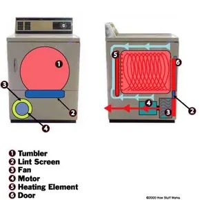
Where Does a Dryer Pull Air From?
You already know the warm, moist air escapes through a hole in the back, routed via a pipe to an exterior vent. But the process starts long before the exhaust. Air actually enters through openings on the outside of the machine. One fan moves everything, but it’s the final step, not the start.
Here is the path the air takes:
- It enters the dryer body through a large opening in the front.
- It is drawn past the heating element and into the tumbler.
- Air moves through the door and is pulled down through the lint screen.
- It travels through a duct in the front and into the fan.
- The fan pushes it into the rear duct, sending it out of your house.
The first component the air hits is the heating element. After entering the body, the air is sucked through the element, then into the clothing tumbler.
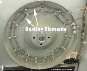
The Heat Source
You are looking at a standard nichrome-wire heating element. It is essentially the same tech found inside a toaster, just scaled up and more robust. If you want to understand the mechanics, look up how toasters work. The principle is identical.
The catch? It pulls serious power. Most dryers run between 4,000 and 6,000 watts. That is not a small load.
Air gets pulled through this wire mesh. Where does it go next?
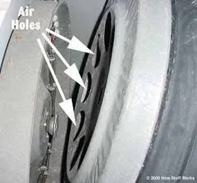
Into the holes at the back of the tumbler. This is where the heat transfers directly into the drum, warming the clothes as they tumble.
Airflow Control and Safety
Look at the metal stamping on the right. It’s the one with the large cutouts. This piece isn’t just decoration. It serves a specific mechanical function. It controls exactly when air can enter the tumbler.
The air doesn’t flow in freely. It must pass through the heating element first. The stamping acts as a barrier until the air has traveled that path. This ensures the incoming air is heated before it reaches the drum.
Without this design, cool air could bypass the heater. That would ruin the drying cycle. The tumbler would run inefficiently. Your clothes might come out damp. Or worse, the dryer could overheat if airflow is restricted elsewhere.
This metal plate directs the flow. It forces the air through the heating coil. Only then does it enter the main chamber. Simple physics. Direct consequence.
Note: The orientation of this stamping matters. If it’s installed backward or loose, airflow can be compromised. Check the fit during reassembly.
You’ll see this part near the back panel. It’s usually secured with a few screws. Make sure you don’t cross-thread them. Tighten them snugly. Not too tight. You don’t want to strip the metal.
If you’re replacing the heating element, check this stamping for damage. Corrosion can block the holes. A bent plate can redirect air incorrectly. Clean it if it’s dirty. Replace it if it’s warped.
It’s a small part. But it’s critical for proper ventilation. Ignore it, and you might deal with longer dry times. Or electrical issues. The stamping keeps the air moving the right way. Through the heat. Into the tumbler.
Where the Heat Actually Goes
Once that hot air hits the wet laundry, it doesn’t just sit there. It pushes through the fabric in the drum, picking up moisture along the way. Then it finds its exit.
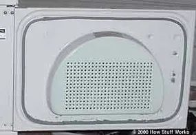
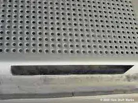
The path isn’t complicated, but it matters. The air flows through the small openings around the door seal. From there, it drops down into the large slot at the bottom of the door frame. This slot funnels the air directly onto the lint screen.
If that lint screen is clogged, the whole airflow chokes. The dryer overheats. The clothes don’t dry.
Clean the screen every single load. Not every three loads. Every time. Clogged filters are the number one reason dryers take forever. They’re also a fire hazard. Lint is fuel. Heat is ignition. You don’t need both.
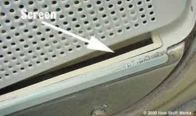
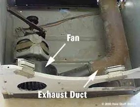
Air doesn’t just sit there in a dryer. It gets pulled through the lint screen first. That’s the first line of defense. From the screen, the flow moves down a duct located at the front of the machine. This path leads directly into the fan assembly.
The fan inside is a centrifugal type. This means it works by spinning rapidly. As the blades rotate, they use centrifugal force to throw air outward. Think of it like a wheel. The air is sucked in from the center. Then, it is forced out through the duct at the back of the dryer. This creates the airflow that dries your clothes.
If that fan slows down or stops, heat builds up. Lint catches fire. The whole system relies on this movement.
Why the Fan Design Prevents Fire
You might wonder why centrifugal fans are used here. They handle high resistance well. Lint clogs ducts. Dust blocks filters. A standard fan might stall. A centrifugal one keeps pushing air even when blocked partially. It maintains pressure. This keeps the dryer from overheating.
But it’s not foolproof. You still have to clean the lint screen. Every time. If you skip it, the screen gets clogged. Air can’t get in. The fan works harder. The motor strains. The heat rises. That’s when things go wrong.
What Makes the Tumbler Spin?
The fan moves air. But what about the clothes? They need to tumble. Without tumbling, clothes clump up. One side stays wet. The other side gets scorched. The next section covers the drive system. It explains how the drum rotates. But for now, focus on the air. If the air isn’t moving, the dryer is just a hot box. And hot boxes with lint are dangerous.
Keep the intake clear. Check the duct behind the dryer once a year. If you see dust buildup, pull the unit out. Vacuum the back. It takes ten minutes. It prevents a $20,000 house fire.
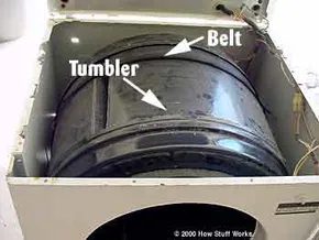
Peel back the panel of a dryer and you might expect to see a complex gearbox. Gears? No. Chains? Not usually. Instead, you’ll find a surprisingly simple setup. The tumbler itself acts as the gear.
Or rather, it acts as a massive pulley.
The motor doesn’t mesh with the drum. It drives a tiny pulley. The ratio between the huge diameter of the tumbler and that small motor pulley does all the work. No intermediate gears needed. Just physics and leverage.
You can see the thin belt wrapped around the tumbler in the image above. That belt is the only thing connecting the motor to the drum. It’s a direct drive. Simple. Efficient. And prone to failure if neglected.
Why Dryers Use Pulleys Instead of Gears
Most people assume rotary motion requires gears. Think of a car transmission. A watch. A bicycle. All gear-driven. But dryers take a different path.
The tumbler is essentially a giant pulley. The motor spins a small pulley. The belt transfers that motion. The size difference creates torque. More rotation, less force. Perfect for tumbling clothes.
Gears add friction. They wear out. They’re expensive. Pulleys? Just a rubber band and two wheels. Cheaper. Quieter. Easier to replace.
This design is standard in most front-load and top-load dryers. You won’t find internal gears on the drum shaft. The drum rotates freely on rollers or glides. The belt pulls it. That’s it.
The Belt’s Role in Dryer Operation
The belt is the heart of the drive system. It’s a thin, reinforced rubber loop. It wraps around the drum and the motor pulley. Sometimes it goes around an idler pulley too. That idler keeps tension. Without tension, the belt slips. The dryer stops turning. Clothes stay wet.
When the belt snaps, the dryer makes a loud squeal. Or nothing. Just silence. And a pile of damp laundry.
Replacing the belt is a common repair. It’s not hard. But you need to access the drum. Which means removing the front or rear panel. Depending on the model.
Tools you’ll need:
– Screwdriver (usually Phillips)
– Pliers
– A new belt (check your model number)
– Flashlight (it gets dark in there)
Safety first. Unplug the dryer. Capacitors can hold charge. Even when unplugged. Be careful.
Idler Pulley Tension System
Many dryers use an idler pulley. It’s not just a passive wheel. It applies pressure. It keeps the belt tight. Without it, the belt would slacken. Slip. Burn out.
The idler pulley spins on a bearing. Bearings fail. When they do, you hear a grinding noise. Or a screech. Sometimes the bearing seizes. The belt breaks. The dryer stops.
Inspect the idler pulley when replacing the belt. Spin it by hand. It should turn smoothly. No grit. No noise. If it’s rough, replace it too. It’s cheap insurance.
Troubleshooting Dryer Belt Issues
How do you know the belt is
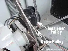
Look closely at the drive system. You’ll see a small silver pulley tucked underneath a larger black one. That silver piece is the one the belt actually hugs. The belt routes through that silver pulley, loops over the black pulley, and finally wraps around the drum itself.
The black pulley isn’t there to drive the belt. It’s there to keep it tight. Think of it as an idler pulley with a spring-loaded arm. When you hook the belt up, you have to pull that black pulley away from its resting position. The spring pushes back. That resistance is what applies tension to the belt. Without that spring tension, the belt would just slip on the motor pulley. No spin. No heat distribution. Just a noisy, useless dryer.
Here is the setup logic. One electric motor handles two jobs. It drives the tumbler. It drives the blower fan. You might think these are separate motors. They are not. They share the same shaft, or at least the same drive train output. The tumbler belt hooks to one part of that output. The fan belt hooks to another.
How the Belt Tension System Works
This is where people mess up. They try to stretch the belt on. They yank it. They break the spring. Or they leave it too loose. The belt slips immediately.
The mechanism relies on the spring pulling the black pulley toward the motor. This creates the gap the belt needs to slide into. But once the belt is in place, that spring tension keeps the belt tight against the drum and the silver pulley.
If you are replacing the belt, you need to replicate this exact geometry. Pull the black pulley away. Slide the belt over the silver pulley first. Then over the black one. Finally, hook it onto the drum. It feels tight. It should feel tight. If you can wiggle the belt more than an inch up and down, it’s too loose. The spring isn’t strong enough to compensate for a stretched belt. You need a new one.
Which Parts Are Involved?
You aren’t just buying a belt. You’re looking at a system.
- The Belt: It’s rubber. Usually reinforced with fabric or cords. It needs to handle heat and friction. Don’t buy the cheapest one on the shelf. It’ll last a month.
- The Silver Pulley: This is the driven pulley on the drum. Check it for cracks. If it’s chipped, the belt will wear out fast.
- The Black Pulley: This is the idler. Check the spring. Is it corroded? Is it snapped? If the spring is weak, the tension is weak. The belt will slip.
- The Motor: It’s usually a universal motor. It spins in both directions depending on the timer settings. But for the belt, direction doesn’t matter. Just make sure the shaft isn’t stripped.
Safety First
Unplug the dryer. Seriously. Don’t just turn off the breaker. Pull the plug. There’s a high-voltage component near the motor. You don’t want to shock yourself while wrestling with a tight belt.
Also, be careful with the spring on the black pulley. It’s under tension. If you
Most people assume a dryer drum spins on bearings. They don’t.
There are no bearings.
So how does it hold the weight of wet towels?
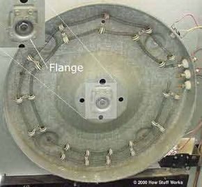
The secret is at the back. A flange connects to a simple bushing. That bushing allows the flange to spin. The tumbler bolts directly to that flange.
This design is cheap. It’s simple. It works—until it doesn’t.
Why Bushings Fail
Bushings wear out. Friction eats them. Over time, the drum wobbles. You hear thumping. You smell burning rubber.
If your dryer is loud, check the bushing. It’s often the culprit.
How to Check the Dryer Bushing
- Unplug the dryer.
- Remove the top panel.
- Look at the back of the drum.
- Find the flange.
- Spin it by hand.
If it grinds, it’s gone. Replace it.
Tools You Need
You won’t need much.
- Screwdriver set
- Nut driver
- Replacement bushing kit
- Work gloves
Safety first. Unplug the machine. Wet clothes are heavy. A slipping tool can hurt.
Which Dryers Use This Design?
Most brands.
Whirlpool. Maytag. GE. Amana.
Check your model. The flange-bushing setup is standard across thousands of units.
Why Not Bearings?
Cost. Complexity. Maintenance.
Bushings are cheaper to make. They don’t need seals. They don’t need grease.
But they wear faster.
Bearings last longer. They cost more. They’re heavier.
For a mass-market appliance, bushings win on price. They lose on longevity.
What Happens When It Breaks
The drum drops slightly. It rubs against the rear panel. Heat builds. Plastic melts.
You might see black dust. That’s worn bushing material.
If you ignore it, the flange cracks. Then the drum fails.
How to Replace It
It’s not hard. But it’s tight.
You’ll need to pull the drum forward. Or remove the rear panel. Depends on the model.
Some drums slide out. Some require disassembly.
Check your service manual. Or find a video for your specific model.
Generic bushings work. OEM parts are better. They fit tighter. They last longer.
The Reality of DIY Repair
You can do this.
But be careful. The drum is heavy. The panels are sharp.
Take your time. Label your screws.
A wobbly dryer is a dangerous dryer. It can tip. It can catch fire.
Don’t risk it. Fix it.
Or call a pro.
Some people prefer to throw the dryer away. New ones cost less than a repair. But that’s wasteful.
Fixing it saves money. It saves landfill space. It gives you something to talk about at dinner.
The bushing is small. The problem is big.
Fix the bushing. Save the dryer.
Or don’t.
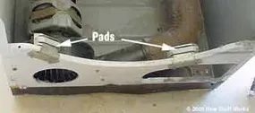
The tumbler doesn’t just spin on metal. It rides on two white plastic pads bolted to the top of the support structure. Friction is kept low. The drum glides. It’s a simple setup, but it matters for longevity.
Controls
Don’t look for a circuit board here. There aren’t any. The electronics are absent. In their place is a mechanical computer. It’s built from gears, cams, electrical contacts, and motors. You turn a dial. The machine responds. Hardwired logic replaces digital code.
Cycle Switch
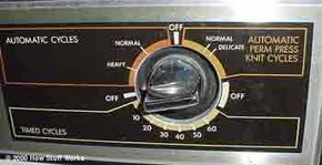
The cycle control knob is the interface. Turn it. Select a cycle. Determine the time. That’s the extent of your input. But what’s happening inside that plastic casing?
The switch isn’t just a simple on/off. It’s a complex mechanism. Rotating the knob engages different cam profiles. These cams press against electrical contacts. The circuit closes or opens based on the position. You’re physically manipulating electricity with mechanical force.
Why does this matter? Because when the electronics fail, you can often fix the mechanical parts. Gears can be replaced. Contacts can be cleaned. A digital board usually means a whole unit swap. The mechanical approach is repairable.
The cycle switch translates your intent into physical motion, which then triggers the electrical sequence.
To see how it works, you need to look inside. Remove the knob. Look at the cam stack. Notice how each position aligns with a specific contact. The length of the cycle is determined by the shape of the cam. The type of cycle is determined by which contacts are engaged.
It’s not intuitive at first. But it’s logical. Once you understand the cam profiles, you can diagnose issues. Is the dryer running too long? Check the cam. Is the heat not turning on? Check the contact.
This is how you service a machine that refuses to die. You learn the language of gears and contacts. You become fluent in mechanical logic. And when the modern stuff breaks, you’re the one who can fix it.
There’s a satisfaction in that. You can feel the clicks. You can see the movement. It’s honest work.
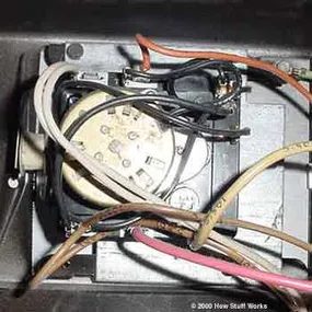
The Motor Inside Your Cycle Switch
Flip the device over. Look at the back. You will see a small motor mounted there. It’s tucked right against the housing.
This isn’t just a decorative piece. It’s the engine that drives the entire mechanism. The motor connects directly to the switch’s internal components. When you press a button or turn a dial, this little unit kicks in. It converts electrical energy into mechanical motion. That motion moves the contacts inside. It opens or closes the circuit. Simple, right?
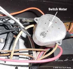
Take a closer look. The image below shows the motor after it has been unscrewed from the switch body. Notice the mounting points. They are usually small screws or plastic clips. If you’re planning to remove it, make sure you have the right screwdriver. A Phillips head is common here. Be careful with the wires. They are often thin and fragile. One tug and you might break a connection.
Why does this matter to you? Because when a cycle switch fails, it’s often this motor that gives out. The gears strip. The windings burn out. The plastic casing cracks. If you know what the motor looks like, you can diagnose the problem faster. You don’t need to replace the whole unit if just the motor is dead. Sometimes, you can source a replacement motor separately. It saves money. It saves time.
The unscrewed state reveals more than just the motor. You can see the attachment brackets. These hold the motor in place while it vibrates slightly during operation. Vibration is normal. But if the brackets are loose, the motor can misalign. Misalignment causes wear. Wear leads to failure. Check the screws before you put it back together. Tighten them gently. Don’t overtighten and strip the threads. Plastic strips easily.
Is it worth the effort? Depends on your skill level. If you’re comfortable with basic electronics, yes. If you’re not, maybe buy a new switch. But understanding how it comes apart helps you avoid future headaches. You’ll know what to look for. You’ll know what breaks. And you’ll know how to fix it. Or at least, you’ll know when to call someone else.
The motor is small. It’s quiet. It does a lot of work. Without it, the cycle switch is just a plastic box. With it, it’s a functional device. Respect the little guy. Treat it well. And if it dies, replace it before it takes the rest of the switch with it.
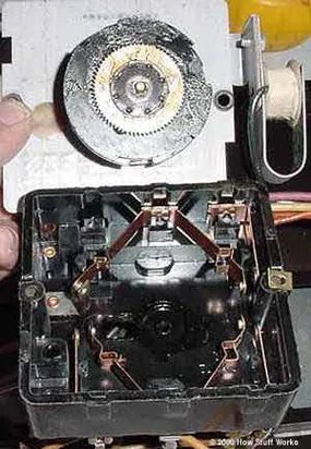
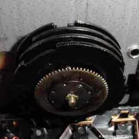
The motor in a mechanical timer doesn’t just spin; it drives a precise sequence of movements. At the heart of this system is a gear on the motor that rotates at a very low speed. This small gear meshes with a gear inside the switch housing. The engagement between these two gears creates a significant reduction in speed. The result is that the switch turns even slower than the input motor itself. This gearing down is essential for accurate timekeeping over hours, not seconds.
The Cam Stack and Dial Connection
The slow-rotating motor directly turns the gear on the dial. This dial is mechanically linked to a critical component: a set of four cams. These cams are stacked vertically on a single axle. Each cam in the stack corresponds to one contact within the switch assembly.
The interaction is straightforward but precise. As the motor turns, the gear on the dial rotates the cam stack. Each cam has a specific profile. When the raised part of a cam pushes against its corresponding contact, it completes or breaks an electrical circuit. This is how a mechanical timer controls appliances like lamps, fans, or heaters. Each of the four contacts is activated by one of the four cams.
The precision of the gear on the motor and the gear inside the switch ensures that the four cams engage the four contacts at the exact intended times.
Why This Design Matters
If you are repairing or replacing a mechanical timer, understanding this gear and cam layout is key. The motor provides the power. The gear on the dial transfers that power. The four cams translate rotation into action. And the four contacts execute the on/off command.
A jammed cam can stop the motor from turning the gear on the dial. Corroded contacts can fail to engage even if the gear inside the switch moves correctly. The gear on the motor must mesh properly with the gear inside the switch to maintain the slow, steady rotation needed for accurate timing.
When the motor fails, the gear on the dial stops. The four cams freeze. The four contacts stay in their last position. No gear inside the switch means no cam movement. The entire system relies on the gear on the motor driving the gear inside the switch, which moves the dial, which rotates the four cams, which operate the four contacts.
It’s a chain. Break one link. The timer stops.
Check the gear on the motor for stripped teeth. Inspect the gear inside the switch for wear. Look at the four cams for debris. Test each of the four contacts for continuity. The motor should turn the gear on the dial smoothly. If it hesitates, the gear inside the switch might be binding.
The four cams must align with the four contacts. Misalignment causes erratic switching. The gear on the motor must drive the gear inside the switch without
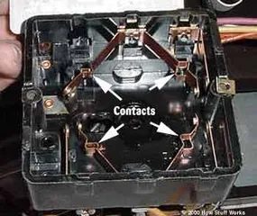
The Geometry of the Contacts
It isn’t random. Each of the four contact points features a distinct bend. They are staggered vertically inside the housing, meaning no two sit at the same elevation. You start at the bottom left contact, which sits at the lowest point. Move counterclockwise and the heights climb. The top left contact claims the highest slot in the stack.
This vertical separation is deliberate. It dictates which cam engages which wire. In the reference images, you can see four distinct cam layers. Each layer aligns precisely with one specific contact height. The top left contact pairs with the highest cam. The bottom left gets the lowest. It’s a mechanical hierarchy built into the box itself.
Tying the Cycle Switch to the Heat Buttons
Think of the cycle switch as the timer for your dryer’s heart. It doesn’t just count seconds; it dictates how long the heating elements stay active. But here is the catch: that timer is hand-in-hand with the heat setting buttons. You can’t pull the lever without engaging the buttons, and the buttons can’t do their job without the switch dictating the duration.
This setup controls which elements are actually firing at any given moment. The logic is straightforward, even if the wiring inside isn’t always obvious to a novice.
- No elements active: Only cool air blows through the drum. This is your air fluff or delicate cycle.
- One element active: The air turns warm. Good for synthetics or things you don’t want to shock with high heat.
- Both elements active: The air gets hot. This is for heavy cottons, towels, and jeans that need serious drying power.
If your dryer runs but never gets warm, the issue rarely lies with the thermostat alone. Start by checking the interaction between the cycle switch and the heat settings. If the timer advances but no heat engages, you might have a broken connection between the switch and the element circuit.
How the Dryer’s Heat Selector Actually Works
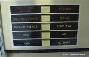
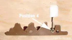
The buttons on your dryer’s control panel aren’t just switches. They’re mechanical interlocks.
Press one of the top four heat settings. It stays depressed.
Press another. The first one pops up. The new button locks in place.
This isn’t random. It’s a dryer heating element selector mechanism built into the front of the machine. Inside the panel, you’ll find a set of metal plates that slide against each other.
Think of them like tumblers in a padlock.
Each plate aligns with a specific circuit. Only one alignment is possible at a time. The plates physically block the other settings. This prevents you from activating two heat levels at once. It keeps the wiring safe. It stops the motor from overheating.
The plates also dictate which heating coils get power.
- Low heat engages only the smaller coil.
- Medium heat activates both coils partially.
- High heat sends full voltage to the main coil.
If the plates are worn, the buttons might stick. Or worse, they might fail to lock. You could end up with no heat. Or too much heat.
Check the plastic retainer clip behind the panel if the buttons feel loose. A loose clip means the plates can’t slide properly.
You don’t need to replace the whole control panel unless the plates are cracked. Sometimes just cleaning the tracks with contact cleaner is enough. Dust builds up. Grit gets in. The plates jam.
If you’re doing this yourself, unplug the dryer first. Seriously. The voltage inside this panel is live even when the machine is off if the timer is in the “run” position.
Remove the screws holding the control console. Lift it back. Don’t yank the wires. Look at the back of the button assembly. You’ll see the metal arms connecting to the timer.
The dryer timer mechanism behind the buttons is what drives the plates. As the timer turns, it pushes the plates forward or back. The heat setting is just the position where the plates stop.
If the dryer runs but doesn’t heat, the problem might not be the elements. It might be the switch behind the buttons. The plates complete the circuit only when fully depressed. If the plastic is stripped, the plate doesn’t push far enough. The switch doesn’t close. No heat.
Replace the control knob if it’s worn. Replace the switch assembly if the contacts are burned. But keep the plates. They’re usually indestructible.
Clean them. Lubricate them lightly with graphite spray. Never use WD-40. It attracts dust. It turns into gunk. You’ll be back here in six months.
The system is simple. Elegant, even. Mechanical logic doing what electronics often fail to do: it enforces rules. You can’t have High and Low at the same time. The metal won’t let you.
Unless the metal is broken.
Then you’re on your own.
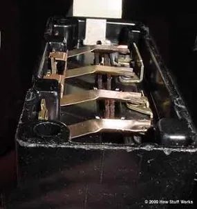
The mechanics inside the toggle
Inside the housing, you are looking at a set of four contacts. It is not magic. It is simple metal. When you click the toggle, you are manipulating a system of plates. These plates move. They open or close different combinations of the contacts.
The position of the toggle determines the electrical path. Press the button one way. Press it the other. The internal geometry shifts.
Visualizing the connection
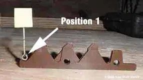
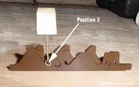
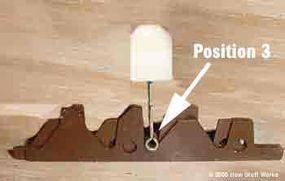
A series of diagrams usually accompanies this explanation. These pictures show the physical reality. They illustrate how pressing the buttons aligns the plates. The alignment changes. This movement raises or lowers the bars that make the contacts.
Think of it like a physical bridge. You are building or breaking a circuit by moving metal bars. The bars are the key. They touch the contacts to complete the path. They pull away to break it. The plates control the height of these bars.
Why four contacts matter
Most standard switches have three terminals. A 4-way switch is different. It needs four contacts to handle the multiple paths. This allows the light to be controlled from more than two locations. The internal bars and plates work in tandem. They create the necessary switching logic.
What you need to know for installation
You do not need to disassemble the switch to install it. But understanding the four contacts helps. You need to know which terminal is common and which are travelers. The internal bars determine this. If you wire it wrong, the switch becomes useless. The plates will move. The contacts will not align correctly. The light will stay off. Or stay on. But never switch.
The bars inside are small. They can bend. Handle the switch with care. Do not force the toggle. If it sticks, the internal plates may be jammed. The contacts might be worn. Replacement is often cheaper than repair. The four contacts are sealed inside. You cannot fix them. You replace the whole unit.
The hidden complexity
It looks simple. A plastic box and a lever. But the four contacts and moving bars do the heavy lifting. They manage the current. They handle the load. When you click the switch, you are trusting this internal mechanism. It works because the plates align the bars with the contacts. Exactly. Every time.
Is it complicated? Only if you try to understand it by looking at the outside. The truth is inside. And it is just metal on metal.
Dual-Temperature Safety Cutoffs
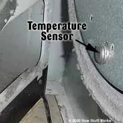
Dryers aren’t just heating chambers. They rely on two distinct temperature shut-off switches to keep things from melting down. These aren’t suggestions. They are hard-wired fail-safes. When the internal temp hits a specific preset, the circuit breaks. Power cuts. The drum stops. Simple, mechanical, and effective.
The first sensor lives near the lint filter. Look at the front panel, partially pulled back. You’ll spot the sensor on the right. On the left, notice the six holes punched into the tumbler’s outer edge. These aren’t decorative. They are timed vents. As the drum rotates, the holes pass directly in front of the sensor, blasting it with hot air. This lets the sensor read the actual air temp inside the drum. If it gets too hot? The sensor triggers the cutoff immediately.
But here is the flaw in that design.
What if the drive belt snaps? The drum stops spinning. The holes never align with the sensor. The sensor sits in cool, stagnant air while the heating element continues to cook everything inside. Or what if the exhaust hose is completely clogged with lint? No air moves through the tumbler. The sensor never feels the heat. It stays cool. It doesn’t trip.
That is why you need the second switch.
The Second Safety Net
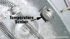
The second sensor sits closer to the heating elements. It watches for the immediate aftermath of a blockage. If airflow stops, the air right next to this sensor heats up fast. It doesn’t wait for the whole drum to get hot. Once the temperature hits a specific trigger point, the sensor cuts the power. It’s a failsafe for when the primary safety measures fail.
Lint Screen Maintenance and Duct Safety
You need to clean the lint screen after every single load. This is non-negotiable. A clogged screen chokes airflow. Choked airflow leads to longer drying times. It also creates a fire hazard. The lint is highly flammable. Keeping the path clear is the first line of defense.
But what if the duct behind the machine is blocked?
A dryer cannot operate efficiently with an obstructed exhaust duct. The moisture has nowhere to go. The heat has nowhere to escape. The dryer works harder. It lasts longer in terms of hours used, but not in terms of lifespan. The risk of overheating jumps significantly. A fire risk is no longer just a possibility; it’s a probability.
More Resources
- Clothes Dryer Reviews
- Buying a Clothes Dryer
- The Dryer Page
- Countertop Microwave Clothes Dryer
- How to install a clothes dryer
- How to vent a clothes dryer
- Repair Clinic: dryer parts and dryer repair advice